Sensor Board Lab
There are two sensor boards. They are identical except that the positions of the red and green LEDs are interchanged.
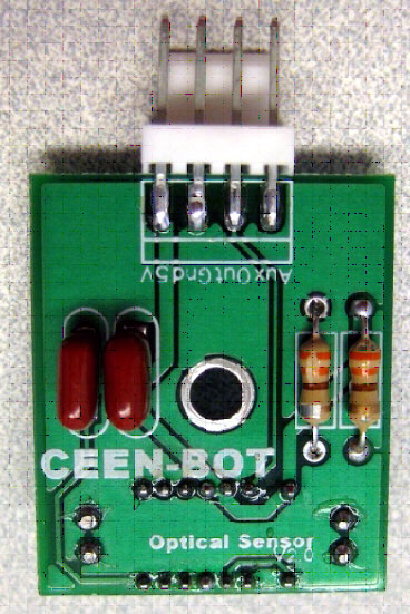
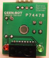
The sensor board has components mounted on both sides. Make sure you place components on the correct side. Use the photos to verify parts placement.
Open the bag of parts for the Sensor board and sort them onto the Parts Map. Do this before you solder any components to minimize the chance of misreading a component's id and soldering it into the wrong location. Solder the components in the order shown on the parts map. The order is basically that the lowest profile items are soldered first. The dashed outlines on the parts map indicate components that must be oriented a specific way.
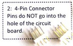
1. Start by soldering the connector. The Connector DOES NOT go into the holes on the circuit board. The leads are placed over the solder area. Melt a drop of solder on one of the pads. Position the connector and heat the lead over the drop of solder to attach the connector. When alignment is correct, solder the remaining leads. View video.
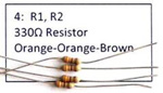
2. The resistors are placed next. The orientation of resistors does not matter. View video.
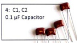
3. The capacitors are placed next. The orientation of these capacitors does not matter. View video.
The remaining components are placed on the back side of the circuit board.
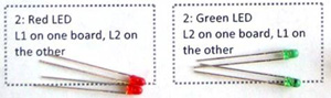
4. The LED colors are opposite on the two boards. The longer lead is the anode (positive) and the shorter is the cathode (negative). The short lead of the LED is placed in the hole adjacent to the flat side of the silk screen symbol. View video.
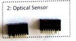
5. The Optical Sensor is the final component. Its leads will allow it to be placed in only the correct orientation. View video.