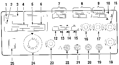
Figure 2 shows the front-panel controls, connectors, and indicators of the CFG280 Function Generator.
Front Panel
Figure 2 shows the front-panel controls, connectors, and indicators
of the CFG280 Function Generator.

1. OVER RANGE LED.
Lights if you apply a frequency above specified limits to the
EXT COUNTER INPUT connector. It also lights if the gate time is
too slow for the incoming signal.
2. GATE LED. Lights
when the frequency counter is making a measurement. The LED will
blink when the counter updates the display.
3. COUNTER READOUT.
This is a five-digit display that shows frequency counter measurements.
The decimal point is automatically placed in the appropriate position,
depending on the measurement and resolution.
4. MULTIPLIER LEDs.
Indicate the frequency multiplication factor of the function generator
outputs. The 10-1M LED indicates a factor from 10 through 106.
You should use the 10-1M LED with the counter readout and FREQUENCY
Range LEDs. The 1 and 0.1 LEDs provide accurate indication for
the two lowest frequency ranges. For example, if the FREQUENCY
dial is set on 2.6 and the 1 LED is lighted, the function generator
output frequency is 2.6 Hz.
5. FREQUENCY Range LEDs.
Indicate the range (either MHz or kHz) of the reading shown on
the counter readout. These LEDs also indicate the frequency range
of the function generator output. For example, if the FREQUENCY
dial is set on 9, the 10-1M LED is lighted, the kHz LED is lighted,
and the counter readout shows .090, then the function generator
output frequency is 0.090 kHz=90Hz.
NOTE. You must have the SOURCE button set on INT (pushed out) to differentiate between the 10, 10^2 10^3 (kHz), 10^4, 10^5, and 10^6 (MHZ) generator output ranges.
6. SEC LED.
Lights when the frequency counter is in PERIOD mode. The counter
readout does not show frequency in hertz, but period in seconds.
For example, if the FREQUENCY dial is set at 4, the 1 multiplier
LED is lighted, and the SEC LED is lighted, the counter readout
displays a value close to 0.250. This indicates the generator
output period is .25 s (the frequency is 4 Hz).
7. MULTIPLIER Buttons.
Set the frequency range. The left button raises the range by a
power of ten and the right button lowers the range by a power
of ten. For example, if the FREQUENCY dial is set to 4.7 and the
output is set to kHz, when you press the left multiplier button
the output frequency will jump from 4.7 X 10³ Hz (4.7 kHz) to
4.7 X 10⁴ Hz (47 kHz).
8. FUNCTION Buttons.
Select the type of waveform generated: sine, triangle, or square.
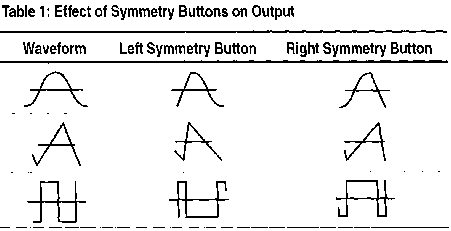
9. Symmetry Buttons.
Select either positive pulse/ramp or negative pulse/ramp (see
Table 1 on page 6 (user manual). When you push either button in,
the output frequency is 1/10 of the value shown on the FREQUENCY
dial. When you push both buttons in, the output frequency is 1/19
of the value shown on the FREQUENCY dial.
10. SWEEP Button. Activates the internal sweep generator, which produces a signal that traverses a range of frequencies. This button enables the SWEEP RATE and SWEEP WIDTH knobs.
You can also feed an external sweep signal into the CFG280 Function Generator through a connector on the rear panel. See External Sweep on page 11 (user manual) for further details.
11. SWEEP RATE Knob.
Adjusts how often the frequency sweep reiterates-the rate at which
the signal traverses the frequencies. If you pull this button
out, the sweep will stop and you can adjust the sweep stop frequency
with the SWEEP WIDTH knob.
12. GATE SEL Button.
Selects the gate time. If the gate time is too slow for the incoming
signal, the OVERRANGE LED lights.
13. ATTN Button.
Selects between two levels of input signals for the EXT COUNTER
INPUT. When you push the button in, the CFG280 Function Generator
attenuates the incoming signal by a factor of ten (the Peak-to-peak
input level must be between 3 V and 42V). When you push the button
out, the function generator does not attenuate the input signal
(the peak-to-peak input level must be between 50 mV and 5 V).
14. SOURCE Button.
Selects between internal and external counter input. When you
push the button in, the counter readout displays the signal frequency
count from the EXT COUNTER INPUT. When you push the button out
the counter readout displays the frequency count of the signal
being generated by the CFG280 Function Generator.
15. MAIN Button.
Selects between two voltage ranges: 0 VP-P to 2 VP-P or 0 VP-P
to 20 VP-P. This control is used with the AMPLITUDE control to
set the voltage level of the MAIN OUT signal.
16. AMPLITUDE Knob.
Adjusts the voltage within the presently selected range. This
control is used with the MAIN control to set the voltage level
of the MAIN OUT signal.
17. DC OFFSET Knob.
Sets the DC level (and therefore the polarity) of the MAIN OUT
signal. This knob has no effect until you pull it out.
18. SWEEP WIDTH Knob.
Adjusts the range of frequencies that are traversed by each sweep.
19. SWEEP OUT BNC.
This connector sends sweep signals that you can adjust with the
sweep controls. You can use a sweep signal to synchronize an external
device such as an oscilloscope.
20. MAIN OUT BNC.
This connector sends sine, triangle, square, and positive and
negative pulse/ramp signals.
21. SYNC OUT BNC.
This connector sends TTL trigger signals. Amplitude and DC offset
adjustments do not affect TTL trigger output.
22. EXT COUNTER INPUT
BNC. This connector can accept external signals with frequencies
between 1 Hz and 100 MHz.
23. FREQ FINE ADJ knob.
Allows small adjustments in output frequency.
24. FREQUENCY Dial.
Determines the frequency of the function generator output, within
the range set by the MULTIPLIER buttons.
25. POWER switch.
Toggles instrument power on and off.
Rear Panel in addition to the line voltage switches, fuse, and power cord receptacle, the items shown in Figure 3 are located on the rear panel.
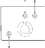
Fig 3: Rear Panel Connections
![]() CAUTION. To
avoid the risk of fire or damage to the CFG280 Function Generator
be sure input equipment is properly grounded before connecting
it to the function generator
CAUTION. To
avoid the risk of fire or damage to the CFG280 Function Generator
be sure input equipment is properly grounded before connecting
it to the function generator
1. GATE INPUT BNC. This connector accepts external gate
signals, which you can use in tone-burst generation. See page
13 (user manual) for details.
2. EXT AM INPUT BNC. This connector accepts external amplitude
modulation signals. See page 12 (user manual) for details.
3. VCF INPUT BNC. This connector accepts external sweep
signals. See page 11 (user manual) for details.
Reference
This section describes several advanced functions of the CFG280
Function Generator. The variety of swept and modulated signals
available from the function generator make it especially useful
for such applications as testing servo-system or amplifier response,
distortion, and stability. It can be used for FM generation, frequency
multiplication, or as a variable, beat-frequency oscillator. It
can be used to generate repetition rates or tone bursts. The square
wave sync and sweep outputs can be used as a source for TTL logic
or to synchronize an external device, such as an oscilloscope.
The CFG280 Function Generator is also useful as a source for amplitude
modulated signals for various purposes.
TTL Signals
To generate a TTL signal, follow these steps:
1. Connect the SYNC OUT connector on the CFG280
Function Generator to the input BNC connector on an oscilloscope
(see Figure #4).
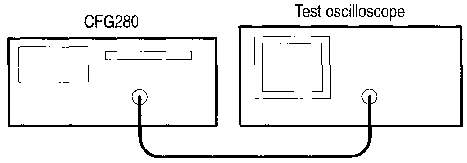
2. Observe the results on the oscilloscope. If necessary,
change the volts per division setting or other controls on the
oscilloscope to acquire a useful signal.
3. Change the FREQUENCY range and rotate the FREQUENCY
dial. Observe how the frequency of the TTL signal changes.
4. Rotate the DC OFFSET knob. Notice that this knob
has no effect on TTL signals.
The DC OFFSET knob has no effect because the DC offset of a TTL signal is standardized for compliance with TTL logic. Signals produced from the SYNC OUT connector are not affected by this knob.
5. Rotate the AMPLITUDE knob. Notice that this knob has no effect on TTL signals.
The AMPLITUDE knob has no effect because the amplitude of a
TTL signal is standardized for compliance with TTL logic.
Internal Sweep
To use the internal sweep function, follow these steps:
1. Connect the MAIN OUT BNC on the CFG280
Function Generator to the device under test, such as a filter
(see Figure 5).
2. Connect the SWEEP OUT connector to one
channel of an oscilloscope (see Figure 5).
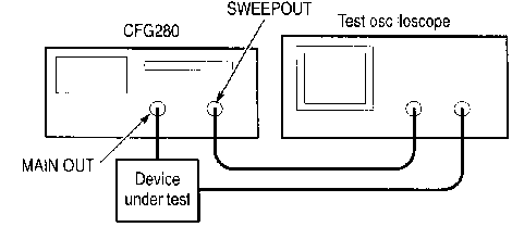
3. Connect another channel of the oscilloscope to the
device under test (see Figure 5).
4. Push the SWEEP button out on the function generator
to deactivate the internal sweep function.
5. Turn the FREQUENCY dial to the desired sweep
start frequency (the lowest point on the sweep).
6. Push the SWEEP button in to enable the internal
sweep function.
7. Pull the SWEEP RATE knob out to lock the function
generator at the sweep stop frequency (the highest point on the
sweep).
8. Adjust the sweep stop frequency with the SWEEP WIDTH
knob.
9. Now push the SWEEP button in to activate the
internal linear sweep. Use the SWEEP RATE knob to adjust
the sweep rate.
External Sweep
To use the external sweep function, follow these steps:
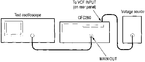
1. Connect the MAIN OUT connector on the
CFG280 Function Generator to the oscilloscope input connector
(see Figure 6).
2. Turn the Frequency Dial to the 0. 1 position.
![]() CAUTION. To
avoid damage to the CFG280, ensure that the maximum voltage into
the rear panel VCF INPUT is no more than ±10 Vpk.
CAUTION. To
avoid damage to the CFG280, ensure that the maximum voltage into
the rear panel VCF INPUT is no more than ±10 Vpk.
3. Connect an external voltage signal to the VCF
INPUT on the rear panel of the instrument (see Figure 6).
4. Push the SWEEP button out to deactivate the internal
sweep function.
When using an external sweep signal, the SWEEP WIDTH and SWEEP RATE knobs have no effect on the signal sweep. Instead, these parameters are controlled entirely by the external signal provided through the rear panel.
Amplitude Modulation
To use the amplitude modulation function, follow these steps.
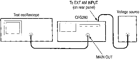
1. Connect the MAIN OUT connector on the
CFG280 Function Generator to the oscilloscope input (see Figure
7).
2. Push the sine wave FUNCTION button.
3. Set the FREQUENCY dial to the desired carrier
frequency.
![]() CAUTION. To
avoid damage to the CFG280 Function Generator ensure that the
maximum voltage into the rear panel VCF INPUT is no more than
5 Vp-p
CAUTION. To
avoid damage to the CFG280 Function Generator ensure that the
maximum voltage into the rear panel VCF INPUT is no more than
5 Vp-p
4. Connect an external voltage signal to the EXT
AM INPUT on the rear panel of the instrument (see Figure 7).
5. Control the amplitude modulation by varying the voltage
level of the external voltage source.
Tone-Burst Generation
and
Stepped Frequency Multiplication
You can use the CFG280 Function Generator as a tone-burst generator or frequency multiplier for checking tone-controlled devices. This application requires another function generator (such as the Tektronix CFG253) to serve as a gating signal source and a ramp generator to serve as a VCF signal source.
1. Connect the MAIN OUT connector on the
CFG280 Function Generator to the oscilloscope input connector
(see Figure 8).
2. Connect the ramp generator output to the VCF
INPUT connector on the rear of the CFG280 Function Generator
(see Figure 8).
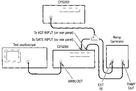
3. Connect the MAIN OUTPUT of the CFG253
to a BNC T connector. Connect the BNC T outputs to the GATE
INPUT connector on the CFG280 Function Generator and the
external input on the ramp generator (see Figure 8).
4. Set the ramp generator to generate the desired ramp
duration and polarity.
5. Adjust the CFG253 Function Generator output period to
the desired number of bursts within the selected ramp duration.
6. Adjust the CFG253 Function Generator output duration
to the desired burst width.
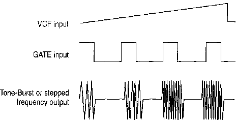
Figure 9: Tone-Burst and Stepped Frequency Typical Waveforms
7. Select the sweep frequency range by adjusting the FREQUENCY dial to one end of the swept range (upper or lower limit, depending on the polarity of the ramp) and adjusting the other end with the RG501 output amplitude.
General Description
The Tektronix CFG280 Function Generator produces low distortion
sine waves, square waves, triangle waves, TTL sync signals, positive
and negative pulses, and ramp waveforms in a frequency range of
0. 1 Hz to 11 MHz. You can also directly control amplitude and
DC offset.
The sweep function makes the output signal traverse a range of frequencies. The START and STOP FREQ control settings determine the sweep rate and sweep width internally or the sweep function can be input from an external DC signal.
A voltage-controlled frequency (VCF) input controls the output frequency from an external voltage source. The output frequency can be swept above or below the selected frequency to a maximum of 100: 1, depending on the polarity and amplitude of the VCF input and the selected output frequency. Provisions are also made for amplitude modulation of the sine wave output from an external source.
An external gate input allows the generator to operate for the duration of an externally applied gating signal. This mode provides either a single cycle output or a train of preselected waveforms, depending on the gating signal width and the function generator frequency setting.
The CFG290 Function Generator has a frequency counter to count the signal frequency of sine, square and triangle waves from 1 Hz to 100 MHz. The frequency counter features one five-digit display with automatic decimal point placement and LED indicators that show the display measurement unit and mode. It can measure periods in seconds or frequencies in kHz or MHz. The front panel controls also provide selectable gate times (resolution) and selectable X 10 attenuation.
The CFG280 has a locking, multi position handle that folds under the instrument. The instrument comes with a power cord, an installed fuse for 115V operation, and this manual.